Variable Speed AccuLink Heat Pumps and Air Conditioners. Variable Speed Alert Codes;

| Led Fault Codes | Solutions |
|---|---|
| 1 Flash | Ambient Temp Sensor is out of range (open/shorted). Initiate a 15 minute forced Defrost after every 60 minutes of runtime. |
| 2 Flash | Coil Temp Sensor is out of range (open/shorted). Initiate a 15 minute forced Defrost after every 60 minutes of runtime. |
| 3 Flash | Low Pressure Switch is open. 3 flash goes away when/if LPCO closes. |
| 4 Flash | Hard Lock Out (can only be cleared with power cycle). Occurs after 4th trip of LPCO. |
| 5 Flash | Soft Lock Out. 5 flash goes away after soft lockout periods expires. |
| 6 Flash | Defrost cycles too close together. Heating Short Cycle Fault triggers 6 flash and 5 flash codes. Follow Soft Lock Out sequence until Hard Lock Out (4 flash) or can clear if conditions no longer exists. |
| 7 Flash | In Timed Defrost mode. Check Ambient sensor placement and verify SOV is operating properly. Implied sensor fault (calibration/range) set after defrost and reset after 15 minutes run time after defrost. |
| 8 Flash | In Timed Defrost mode. Check Coil sensor placement and verify SOV is operating properly. Outdoor temperature is below -7'F |
| 9 Flash | Low Ambient Soft Lockout. Outdoor temperature dropped below 3F. (OFF at -7F/ON at 3F) Outdoor temperature is below -7'F |
| 13 Flash | Fault with the external temperature sensor |
| 17 Flash | High pressure problem |
| Amber light on | Unit requires refrigerant. |
| Green light on | Unit is operating normally. |
- Initiate Adaptive/Timed Defrost so long as Coil Temp Sensor is functional. Monitor actual time in defrost and add or reduce run time until next forced defrost based on achieving a 4 minute (+/- 1) defrost period.
- 1st LPCO trip results in a 15 minute soft lockout period.
- If both Coil Temp Sensor and Ambient Temp Sensor are failed, initiate a 15 minute forced defrost after ever 60 minutes of run time.
- Do not track if Y cycles off or if defrost takes 15 minutes (Max Time Override). Ambient Sensor reading is monitored at the end of defrost and should not deviate more than +/-5F. Ambient Sensor must report a lower temperature than the Coil Sensor immediately after defrost (Coil Sensor should always be higher than Ambient Sensor when defrost terminates).
- Do not track if Y cycles off or if defrost takes 15 minutes (Max Time Override). Coil Sensor reading is monitored at the end of defrost and reading must be less than Ambient Sensor after 15 minutes of run time
- Once ambient drops to -7F or lower, wait 5 minutes before soft lockout begins. During soft lock out the Y signal passes through to the X2 output. Resume operation when ambient temperature rises to 3F or higher and after a 15 minute soft lockout period expires.
- During a Hard Lockout, the X2 relay opens so that the Y signal does not pass though.
Fault Code Recovery
On power up, last 4 faults, if any, will be flashed on the red LED. The newest fault detected will flash first and the oldest last. There will be a 2 second delay between fault code flashes. Solid red LED error codes will not be displayed. The Green LED will be on solid during last fault recovery. At any other time the control is powered, the Green LED indicator light will operate as shown in Table 14 and the red LED will flash LitePort data (one flash) every 20 seconds.
Fault Code Reset
The last 4 fault codes can be erased from memory by powering up the control with “G” energized and then applying “R” to the “W1” terminal 3 times within 6 seconds. The control will acknowledge the reset by turning on the red LED for 2 seconds.
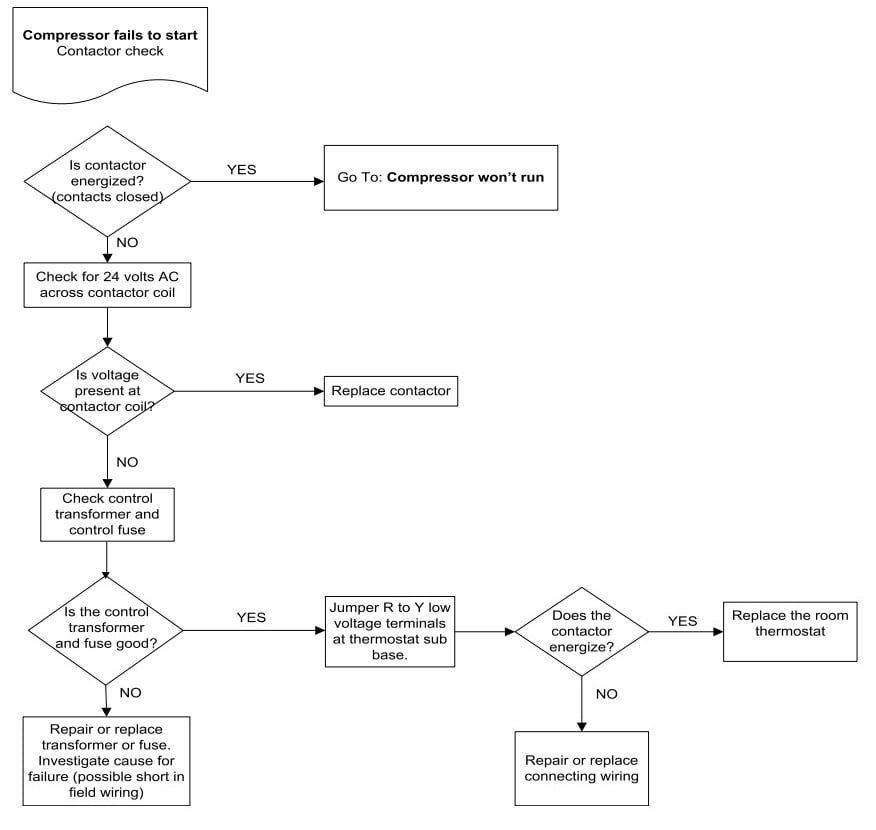
Troubleshooting: Compressor fails to start, Contactor check
Comments